Quantcast
Channel: Examtut
Viewing all 26 articles
Browse latest View live

CCENT Simulation RIPv2

$
0
0

Central Florida Widgets recently installed a new router in their Apopka office. Complete the network installation by performing the initial router configurations and configuring RIPv2 routing using the router command line interface (CLI) on the Apopka router.

ripsim

Configure the router per the following requirements:

  • Name of the router is Gotha
  • Enable-secret password is cisco
  • The password to access user EXEC mode using the console is class
  • The password to allow telnet access to the router is class
  • IPv4 addresses must be configured as follows:
    • Ethernet network 209.165.201.0/27 – router has second assignable host address in subnet.
    • Serial network is 192.0.2.128/28 – router has last assignable host address in the subnet.
  • Interfaces should be enabled.
  • Routing protocol is RIPv2.

Instruction:

To configure the router (Gotha) click on the console host icon that is connected to a router by a serial console cable (shown in the diagram as a dashed black line).

Each of the windows can be minimized by clicking on the [-]. You can also reposition a window by dragging it by the title bar.

The “Tab” key and most commands that use the “Control” or “Escape” keys are not supported and are not necessary to complete this simulation. The help command does not display all commands of the help system.


Explanation:

Step1:

Click on the console host.

Router>
Configure the new router as per the requirements provided in Lab question


Requirement 1:
Name of the router is Gotha

Router>en
Router# conf t
Router(config)# hostname Gotha
Gotha(config)#


Requirement 2:
Enable-secret password is cisco

Gotha(config)# enable secret cisco


Requirement 3:
The password to access user EXEC mode using the console is class

Gotha(config)# line con 0
Gotha(config-line)# password class
Gotha(config-line)# login
Gotha(config-line)# exit
Gotha(config)#

Requirement 4:
The password to allow telnet access to the router is class

Gotha(config)# line vty 0 4
Gotha(config-line)# password class
Gotha(config-line)# login
Gotha(config-line)# exit
Gotha(config)#

Requirement 5:
a. Ethernet network 209.165.202.128 /27 – Router has the last assignable host address in subnet.

rip

This IP address (209.165.201.158) which we need to configure on Fast Ethernet0/0 of the router using the subnet mask 255.255.255.224

Gotha(config)# interface fa0/0
Gotha(config-if)# ip address 209.165.201.158 255.255.255.224
Gotha(config-if)#no shutdown
Gotha(config-if)#exit


b. Serial Network is 192.0.2.16 /28 - Router has the last assignable host address in subnet.

ripsim2

Serial Network is 192.0.2.16 /28 - Router has the last assignable host address in subnet. We

need to configure Last assignable host address(192.0.2.30) on serial 0/0/0 using the subnet mask 255.255.255.240

Gotha(config)#interface serial 0/0/0
Gotha(config-if)#ip address 192.0.2.30 255.255.255.240
Gotha(config-if)#no shutdown
Gotha(config-if)#exit


Requirement 6:

Router protocol is RIPv2

Need to enable RIPv2 on router and advertise its directly connected networks

Gotha(config)#router rip
Gotha(config-router)# version 2
Gotha(config-router)# no auto-summary
Gotha(config-router)#network 192.0.2.16
Gotha(config-router)#network 209.165.202.128
Gotha(config-router)#end

Step 7:

Important please do not forget to save your running-config to startup-config

Gotha# copy run start


Which entry will be in the ARP cache of HostA to support this transmission?

$
0
0

Refer to the exhibit. After HostA pings HostB, which entry will be in the ARP cache of HostA to support this transmission?


231


Aimage
Bimage
Cimage
Dimage
Eimage
Fimage


Answer : D

Explanation:

ARP – Address Resolution Protocol
It is used to find the MAC address from known IP address.
ARP is used to convert an IP address to a physical address such as an Ethernet address (MAC Address).

If a host or device transmitting data to another network (not same IP subnet), then data will forward to default gateway.

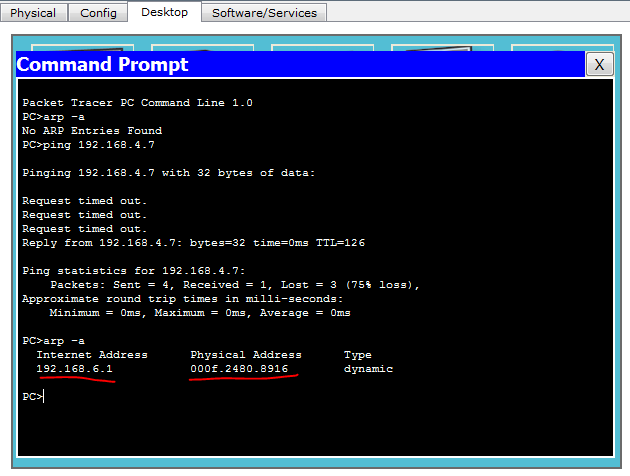
In the exhibit, the Host A is transmitting data to Host B, then Host A forward the packet to Router1, for that communication Host A needs MAC address of Router1. If we check the ARP cache of Host A, we will get 192.168.6.1 – 000f.2480.8916.

Download the topology and check it for your own: https://app.box.com/s/hzyjmaxrjjegm3zac9xo

Screenshots

image

Click HostA > Desktop > Command Prompt

Commands

arp -aused to view the arp cache
ping 192.168.4.7used to check the connectivity to HostB


image

What is the result of setting the no login command?

$
0
0

Refer to the exhibit. What is the result of setting the no login command?

image


A. Telnet access is denied.
B. Telnet access requires a new password at the first login.
C. Telnet access requires a new password.
D. There is a virtually limitless supply of IP addresses.

Answer : D

Explanation:

No Login command allows users to Telnet into a router with no password. Either way, something has to be configured for Telnet to work. Also, you cannot enter privileged mode (which is the IOS EXEC mode that allows you to view or change the configuration on a router) from Telnet unless an Enable password is set. These are very basic features of Cisco routers and allow only some security.


Screenshots

image

I just typed “ping 192.168.118.66”, Router R1 IP address:

image


image

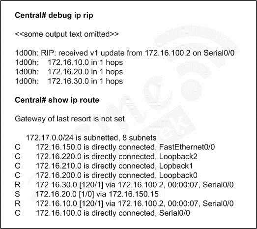
The remote networks 172.16.10.0, 172.16.20.0, and 172.16.30.0 are accessed through the Central router's serial 0/0 interface.

$
0
0
The network administrator has found the following problem.

74
The remote networks 172.16.10.0, 172.16.20.0, and 172.16.30.0 are accessed through the Central router's serial 0/0 interface.
No users are able to access 172.16.20.0. After reviewing the command output shown in the graphic, what is the most likely cause of the problem?

A. no gateway of last resort on Central
B. Central router's not receiving 172.16.20.0 update
C. incorrect static route for 172.16.20.0
D. 172.16.20.0 not located in Central's routing table


Answer : C

Explanation :
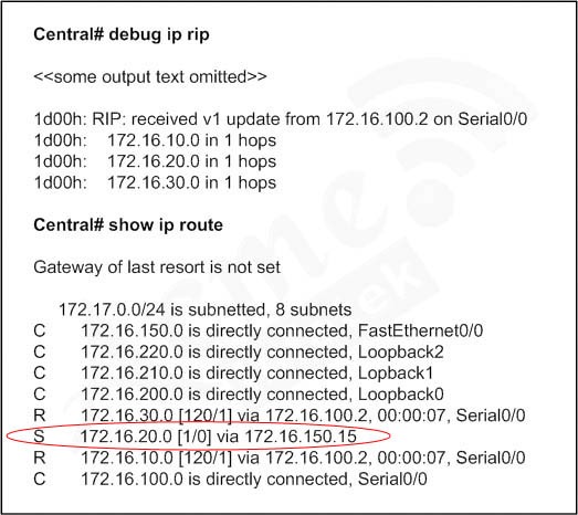
A static route for 172.16.20.0 is mapped to 172.16.150.15.

The route to 172.16.150.0 is mapped to Fa0/0. So if a data from Fast Ethernet 0/0 to 172.16.20.0 network raised, then Central router will loop the data to Fast Ethernet 0/0 itself.

74_Answer

Do we need to put the answer in Drag & Drop in order IN REAL EXAM?

$
0
0

Answer is NO

Example :

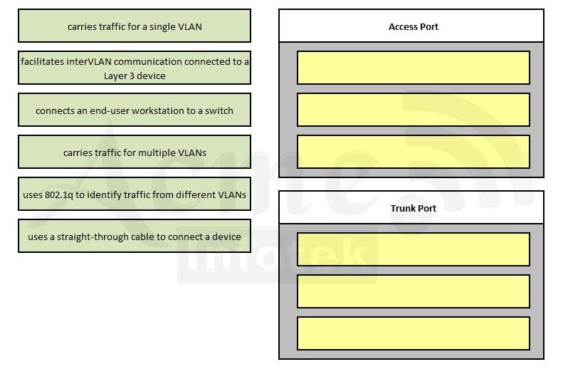
Drag the options on the left under the type of switch port that they describe on the right.

4


Answer is

image

You just have to drag the features from the left to the appropriate port on the right. There is no specification in the question about move the question in appropriate order. If you put carries traffic for a single VLAN in third place of Access Port. In real exam this is not an error.

But in this VCE software, if we put carries traffic for single VLAN in the third place of Access Port, then it marked the question as Wrong.

So cheers guys.

CCNA NAT Simulation

$
0
0

A network associate is configuring a router for the Weaver company to provide internet access. The ISP has provided the company six public IP addresses of 198.18.184.105 - 198.18.184.110. The company has 14 hosts that need to access the internet simultaneously. The hosts in the company LAN have been assigned private space addresses in the range of 192.168.100.17 – 192.168.100.30.

natq

The following have already been configured on the router:

  • The basic router configuration
  • The appropriate interfaces have been configured for NAT inside and NAT outside
  • The appropriate static routes have also been configured (since the company will be a stub network, no routing protocol will be required.)
  • All passwords have been temporarily set to “cisco”


The task is to complete the NAT configuration using all IP addresses assigned by the ISP to provide internet access for the hosts in the weaver LAN. Functionality can be tested by clicking on the host provided for testing.

Configuration information:

Router name-Weaver
Inside global addresses-198.18.184.105 – 198.18.184.110 /29
Inside local addresses-192.168.100.17 – 192.168.100.30 /28
Number of inside hosts-14


Answer :

Step 1: Router Name

Router>enable
Router#configure terminal
Router(config)#hostname Weaver
Weaver(config)#


Step 2: NAT Configuration

Weaver(config)#access-list 10 permit 192.168.100.16 0.0.0.15
Weaver(config)#ip nat pool  mynatpool 198.18.184.105 198.18.184.110 netmask 255.255.255.248
Weaver(config)#ip nat inside source list 10 pool mynatpool overload
Weaver(config)#end


Step 3: Save Configuration

Weaver#copy run start


Verification:

We can verify the answer by pinging the ISP IP Address (192.0.2.114) from Host for testing.

Click “Host for testing”

In command prompt, type “ping 192.0.2.114”. If ping succeeded then the NAT is working properly.


Screen Shots:

nat1


nat2


nat3


To download this Lab: https://app.box.com/s/ljdgzhhzaubocmmutjje

Access Control List (ACL) Simlet

$
0
0


acl2

An administrator is trying to ping and telnet from Switch to Router with the results shown below:

acl2result


For this question we only need to use the show running-config command to answer all the questions below:

Router>enable
Router#show running-config

p1

p2

p3 

p4


Question 1

Which will fix the issue and allow ONLY ping to work while keeping telnet disabled?

A. Correctly assign an IP address to interface fa0/1
B. Change the ip access-group command on fa0/0 from “in” to “out”
C. Remove access-group 106 in from interface fa0/0 and add access-group 115 in.
D. Remove access-group 102 out from interface s0/0/0 and add access-group 114 in
E. Remove access-group 106 in from interface fa0/0 and add access-group 104 in


Answer : E

Explanation:

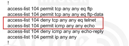
a1

The question was not about FTP so skip line #1 and line #2.
The line #3 denies telnet traffic and line #4 permits icmp-echo traffic.
Line #5 denies echo-reply traffic. If any device pings a device that attached to Fa0/0, the packet will be denied.
Line #6 permits all other traffic.


Question 2:

What would be the effect of issuing the command ip access-group 114 in to the fa0/0 interface?

A. Attempts to telnet to the router would fail
B. It would allow all traffic from the 10.4.4.0 network
C. IP traffic would be passed through the interface but TCP and UDP traffic would not
D. Routing protocol updates for the 10.4.4.0 network would not be accepted from the fa0/0 interface

Answer: B

Explanation:

a2

There is only one command that is associated with access-list 114 and it is access-list 114 permit ip 10.4.4.0 0.0.0.255any. This command will permit traffic from 10.4.4.0 /24 network.


Question 3:

What would be the effect of issuing the command access-group 115 in on the s0/0/1 interface?

A. No host could connect to Router through s0/0/1
B. Telnet and ping would work but routing updates would fail.
C. FTP, FTP-DATA, echo, and www would work but telnet would fail
D. Only traffic from the 10.4.4.0 network would pass through the interface

Answer: A


Explanation:

a4


The above command will only the IP (0.0.0.0). Also there is no such IP address exists.

The wildcard mask of access-list 115 is 255.255.255.0, means that only host with IP addresses x.x.x.0 will be accepted. If the 4th part of an IP address is 0, then definitely it would be a network address. So no host can communicate with other network using S0/0/1 interface.

But it will accept the packet with source IP address – 10.10.0.0/8. The 4th octet is 0, and is not a network address but a valid IP address. So confusion... confusion... Anyhow other 3 choices (B, C, D) will definitely not the answer and Choice A is closest to the result, So the Answer is A. 


CCNP (642-902) OSPF Simulation

$
0
0

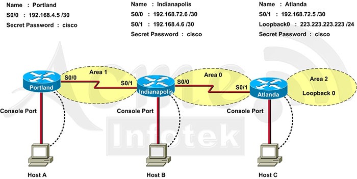
OSPF is configured on routers Indianapolis and Atlanta. Indianapolis’s S0/0 Interface and Atlanta's S0/1 interface are in Area 0. Atlanta’s Loopback0 interface is in Area 2.

ospf

You task is to configure the following:

  • Portland’s S0/0 interface in Area 1
  • Indianapolis’s S0/1 interface in Area 1
  • Use the appropriate mask such that ONLY Portland’s S0/0 and Indianapolis’s S0/1 could be in Area 1.
  • Area 1 should not receive any external or inter-area routes (except the default route).


To download this lab : https://app.box.com/s/izbu1wcbjxdz32hsa1gx

Answer:

Portland Configuration:

Task 1: Portland’s S0/0 interface in Area 1
Task 3: Use the appropriate mask such that ONLY Portland’s S0/0 and Indianapolis’s S0/1 could be in Area 1.


The Portland’s S0/0 IP Address is 192.168.4.5/30. So, we need to find the network address and wildcard mask of 192.168.4.5/30 in order to configure the OSPF.

IP Address : 192.168.4.5 /30
Subnet Mask : 255.255.255.252

Here subtract 252 from 2565, 256-252 = 4, hence the subnets will 4 increment. Like 0, 4, 8, 12, ...

Lets find the 4th octet of Network Address:

SubnetNetworkBroadcast
003
147
2811
31215
41619
5......


The 4th octet of IP address (192.168.4.5) belongs to subnet 1 ( 4 to 7).

Network Address : 192.168.4.4
Broadcast Address : 192.168.4.7


Lets find the wildcard mask of /30.

Subnet Mask : (Network Bits – 1’s, Host Bits – 0’s)

/3011111111111111111111111111111100
 255255255252


Wildcard Mask : (Network Bits – 0’s, Host Bits – 1’s)

/3000000000000000000000000000000011
 0003


First check your OSPF Process Number by using the command:

Portland>enable
Portland#show run
<output omitted>
!
router ospf 1
!


Portland>enable
Password:
Portland#
conf t
Portland(config)#router ospf 1


Portland(config-router)#network 192.168.4.4 0.0.0.3 area 1

Task 4: Area 1 should not receive any external or inter-area routes (except the default route).

Portland(config-router)#area 1 stub
Portland(config-router)#end
Portland#copy run start


Indianapolis Configuration:

Indianapolis>enable
Password: cisco
Indianapolis#conf t
Indianapolis(config)#router ospf 1

Task 2: Indianapolis’s S0/1 interface in Area 1

Indianapolis(config-router)#network 192.168.4.4 0.0.0.3 area 1

Task 4: Area 1 should not receive any external or inter-area routes (except the default route).
In order to accomplish Task 4, we must stop LSA Type 5 if we don’t want to send external routes. And if we don’t want to send inter-area routes, we have to stop LSA Type 3 and Type 4. Therefore we have to configure area 1 as a totally stubby area.

Indianapolis(config-router)#area 1 stub no-summary

Indianapolis(config-router)#end
Indianapolis#copy run start


CCNP (642-902) EIGRP STUB Simulation

$
0
0

By increasing the first distant office, JS manufactures has extended their business. They configured the remote office router (R3) from which they can reach all Corporate subnets. In order to raise network stableness and lower the memory usage and broadband utilization to R3, JS manufactures makes use of route summarization together with the EIGRP Stub Routing feature. Another network engineer is responsible for the implementing of this solution. However, in the process of configuring EIGRP stub routing connectivity with the remote network devices off of R3 has been missing.

Presently JS has configured EIGRP on all routers in the network R2, R3, and R4. Your duty is to find and solve the connectivity failure problem with the remote office router R3. You should then configure route summarization only to the distant office router R3 to complete the task after the problem has been solved.
The success of pings from R4 to the R3 LAN interface proves that the fault has been corrected and the R3 IP routing table only contains two 10.0.0.0 subnets.


Topology:

eigrptopology


Answer:

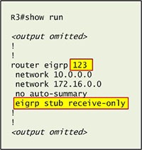
First we have to figure out why R3 and R4 can not communicate with each other. Use the show running-config command on router R3.

eigrp
Notice that R3 is configured as a stub receive-only router. The receive-only keyword will restrict the router from sharing any of its routes with any other router in that EIGRP autonomous system. This keyword will also prevent any type of route from being sent. Therefore we will remove this command and replace it with the eigrp stub command:
R3# configure terminal R3(config)# router eigrp 123 R3(config-router)# no eigrp stub receive-only R3(config-router)# eigrp stub
R3(config-router)#
end

Now R3 will send updates containing its connected and summary routes to other routers. Notice that the eigrp stub command equals to the eigrp stub connected summary because the connected and summary options are enabled by default.
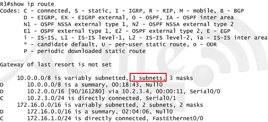
Next we will configure router R3 so that it has only 2 subnets of 10.0.0.0 network. Use the show ip route command on R3 to view its routing table

ee1


Because we want the routing table of R3 only have 2 subnets so we have to summary sub-networks at the interface which is connected with R3, the s0/0 interface of R4.

There is one interesting thing about the output of the show ip route shown above: the 10.2.3.0/24, which is a directly connected network of R3. We can’t get rid of it in the routing table no matter what technique we use to summary the networks. Therefore, to make the routing table of R3 has only 2 subnets we have to summary other subnets into one subnet.

In the output if we don’t see the summary line (like 10.0.0.0/8 is a summary…) then we should use the command ip summary-address eigrp 123 10.2.0.0 255.255.0.0 so that all the ping can work well.

In conclusion, we will use the ip summary-address eigrp 123 10.2.0.0 255.255.0.0 at the interface s0/0 of R4 to summary.

R4> enableR4# conf t
R4(config)# interface s0/0 R4(config-if)#
ip summary-address eigrp 123 10.2.0.0 255.255.0.0

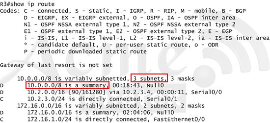
Now we jump back to R3 and use the show ip route command to verify the effect, the output is shown below:

ee2


Note: But please notice that the ip addresses and the subnet masks in your real exam might be different so you might use different ones to solve this question.
Just for your information, notice that if you use another network than 10.0.0.0/8 to summary, for example, if you use the command ip summary-address eigrp 123 10.2.0.0 255.255.0.0 you will leave a /16 network in the output of the show ip route command.

ee3


But in your real exam, if you don’t see the line "10.0.0.0/8 is a summary, Null0" then you can summary using the network 10.2.0.0/16. This summarization is better because all the pings can work well.
Finally don’t forget to use the copy run start command on routers R3 and R4 to save the configurations.

R3(config-if)# end
R3#
copy run start
R4(config-if)# end
R4#
copy run start

Note : If copy run start command doesn’t work then use write memory.

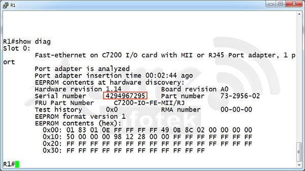
Which two privileged mode Cisco IOS commands can be used to determine a Cisco router chassis serial number? (Choose two.)

$
0
0

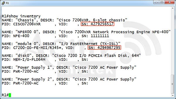
Which two privileged mode Cisco IOS commands can be used to determine a Cisco router chassis serial number? (Choose two.)

A. show inventory
B. show flash:filesys
C. dir flash:|include chassis
D. show diag
E. show controllers


Answer : A, D


Choice A

The “chassis” hardware serial number section designates the serial number that is physically on the router.

r1

Choice D

The show diag command returns the following information about a router and its adaptors/modules:

  • Hardware version
  • Board revision
  • RMA number and history
  • Chassis serial number
  • Cisco field replaceable unit (FRU) number (a good identifiable part number for the device)
  • Cisco part number (the actual part number of the device)
  • Technical registers of the backplane, including power supply and temperature status (not readable by this command)
  • Ports built into the motherboard of the device
  • Hardware versions, serial numbers, and part numbers for WIC cards in the device
  • Part numbers, port information, and serial numbers for network modules (NMs) inserted in the device


r2

CCNA Routing and Switching (200-120)

$
0
0


IMG2 CCNA Composite Exam: The 200-120 CCNAX is the composite exam associated with the Cisco CCNA Routing and Switching certification. Candidates can prepare for this exam by taking the Interconnecting Cisco Networking Devices: Accelerated (CCNAX) v2 course. This exam tests a candidate's knowledge and skills required to install, operate, and troubleshoot a small to medium size enterprise branch network. The topics include all the areas covered under ICND 1 and ICND2 Exams.

Exam Number200-120
Associated CertificationCCNA Routing and Switching
Duration90
Questions50 - 60
LanguageEnglish


The following topics are general guidelines for the content likely to be included on the Cisco Certified Network Associate exam. However, other related topics may also appear on any specific delivery of the exam. In order to better reflect the contents of the exam and for clarity purposes, the guidelines below may change at any time without notice.

Operation of IP Data Networks

  • Operation of IP Data Networks
  • Recognize the purpose and functions of various network devices such as Routers, Switches, Bridges and Hubs.
  • Select the components required to meet a given network specification.
  • Identify common applications and their impact on the network
  • Describe the purpose and basic operation of the protocols in the OSI and TCP/IP models.
  • Predict the data flow between two hosts across a network.
  • Identify the appropriate media, cables, ports, and connectors to connect Cisco network devices to other network devices and hosts in a LAN

LAN Switching Technologies

  • Determine the technology and media access control method for Ethernet networks
  • Identify basic switching concepts and the operation of Cisco switches.
    • Collision Domains
    • Broadcast Domains
    • Types of switching
    • CAM Table
  • Configure and verify initial switch configuration including remote access management.
    • Cisco IOS commands to perform basic switch setup
  • Verify network status and switch operation using basic utilities such as ping, telnet and ssh.
  • Identify enhanced switching technologies
    • RSTP
    • PVSTP
    • Ethercnannels
  • Describe how VLANs create logically separate networks and the need for routing between them.
    • Explain network segmentation and basic traffic management concepts
  • Configure and verify VLANs
  • Configure and verify trunking on Cisco switches
    • DTP
    • Auto negotiation
  • Configure and verify PVSTP operation
    • describe root bridge election
    • spanning tree mode

IP addressing (IPv4 / IPv6)

  • Describe the operation and necessity of using private and public IP addresses for IPv4 addressing
  • Identify the appropriate IPv6 addressing scheme to satisfy addressing requirements in a LAN/WAN environment.
  • Identify the appropriate IPv4 addressing scheme using VLSM and summarization to satisfy addressing requirements in a LAN/WAN environment.
  • Describe the technological requirements for running IPv6 in conjunction with IPv4 such as dual stack
  • Describe IPv6 addresses
    • Global unicast
    • Multicast
    • Link local
    • Unique local
    • eui 64
    • autoconfiguration


IP Routing Technologies

  • Describe basic routing concepts
    • CEF
    • Packet forwarding
    • Router lookup process
  • Describe the boot process of Cisco IOS routers
    • POST
    • Router bootup process
  • Configure and verify utilizing the CLI to set basic Router configuration
    • Cisco IOS commands to perform basic router setup
  • Configure and verify operation status of a device interface, both serial and ethernet
  • Verify router configuration and network connectivity
    • Cisco IOS commands to review basic router information and network connectivity
  • Configure and verify routing configuration for a static or default route given specific routing requirements
  • Manage Cisco IOS Files
    • Boot preferences
    • Cisco IOS image(s)
    • Licensing
      • Show license
      • Change license
  • Differentiate methods of routing and routing protocols
    • Static vs. Dynamic
    • Link state vs. Distance Vector
    • Administrative distance
    • split horizon
    • metric
    • next hop
    • ip routing table
    • Passive Interfaces
  • Configure and verify OSPF (single area)
    • Benefit of single area
    • neighbor adjacencies
    • OSPF states
    • Discuss Multi area
    • Configure OSPF v2
    • Configure OSPF v3
    • Router ID
    • Passive interface
    • LSA types
  • Configure and verify EIGRP (single AS)
    • Feasible Distance / Feasible Successors /Administrative distance
    • Feasibility condition
    • Metric composition
    • Router ID
    • Auto summary
    • Path selection
    • Load balancing
      • Equal
      • Unequal
    • Passive interface
  • Configure and verify interVLAN routing (Router on a stick)
    • sub interfaces
    • upstream routing
    • encapsulation
  • Configure SVI interfaces


IP Services

  • Configure and verify DHCP (IOS Router)
    • configuring router interfaces to use DHCP
    • DHCP options
    • excluded addresses
    • lease time
  • Describe the types, features, and applications of ACLs
    • Standard
      • Sequence numbers
      • Editing
    • Extended
    • Named
    • Numbered
    • Log option
  • Configure and verify ACLs in a network environment
    • Named
    • Numbered
    • Log option
  • Identify the basic operation of NAT
    • Purpose
    • Pool
    • Static
    • 1 to 1
    • Overloading
    • Source addressing
    • One way NAT
  • Configure and verify NAT for given network requirements
  • Configure and verify NTP as a client
  • Recognize High availability (FHRP)
    • VRRP
    • HSRP
    • GLBP
  • Configure and verify Syslog
    • Utilize Syslog Output
  • Describe SNMP v2 & v3


Network Device Security

  • Configure and verify network device security features such as
    • Device password security
    • Enable secret vs enable
    • Transport
    • Disable telnet
    • SSH
    • VTYs
    • Physical security
    • Service password
    • Describe external authentication methods
  • Configure and verify Switch Port Security features such as
    • Sticky MAC
    • MAC address limitation
    • Static / dynamic
    • Violation modes
      • Err disable
      • Shutdown
    • Protect restrict
    • Shutdown unused ports
    • Err disable recovery
    • Assign unused ports to an unused VLAN
    • Setting native VLAN to other than VLAN 1
  • Configure and verify ACLs to filter network traffic
  • Configure and verify an ACLs to limit telnet and SSH access to the router


Troubleshooting

  • Identify and correct common network problems
  • Utilize netflow data
  • Troubleshoot and correct common problems associated with IP addressing and host configurations.
  • Troubleshootand Resolve VLAN problems
    • identify that VLANs are configured
    • port membership correct
    • IP address configured
  • Troubleshoot and Resolve trunking problems on Cisco switches
    • correct trunk states
    • correct encapsulation configured
    • correct vlans allowed
  • Troubleshoot and Resolve Spanning Tree operation issues
    • root switch
    • priority
    • mode is correct
    • port states
  • Troubleshoot and Resolve routing issues
    • routing is enabled
    • routing table is correct
    • correct path selection
  • Troubleshoot and Resolve OSPF problems
    • neighbor adjancies
    • Hello and Dead timers
    • OSPF area
    • Interface MTU
    • Network types
    • Neighbor states
    • OSPF topology database
  • Troubleshoot and Resolve EIGRP problems
    • neighbor adjancies
    • AS number
    • Load balancing
    • Split horizon
  • Troubleshoot and Resolve interVLAN routing problems
    • Connectivity
    • Encapsulation
    • Subnet
    • Native VLAN
    • Port mode trunk status
  • Troubleshoot and Resolve ACL issues
    • Statistics
    • Permitted networks
    • Direction
      • Interface
  • Troubleshoot and Resolve WAN implementation issues
    • Serial interfaces
    • PPP
    • Frame relay
  • Troubleshoot and Resolve Layer 1 problems
    • Framing
    • CRC
    • Runts
    • Giants
    • Dropped packets
    • Late collision
    • Input / Output errors
    • Monitor NetFlow statistics
  • Troubleshoot etherchannel problems


WAN Technologies

  • Identify different WAN Technologies
    • Metro Ethernet
    • VSAT
    • Cellular 3G / 4G
    • MPLS
    • T1 / E1
    • ISDN
    • DSL
    • Frame relay
    • Cable
    • VPN
  • Configure and verify a basic WAN serial connection
  • Configure and verify a PPP connection between Cisco routers
  • Configure and verify Frame Relay on Cisco routers
  • Implement and troubleshoot PPPoE

CCNA – Chapter 1

$
0
0

Question 1
Which layer in the OSI reference model is responsible for determining the availability of the receiving program and checking to see if enough resources exist for that communication?

A. transport
B. network
C. presentation
D. session
E. application

Answer : E

Explanation:

The application layer supports application and end-user processes. Communication partners are identified, quality of service is identified, user authentication and privacy are considered, and any constraints on data syntax are identified. Everything at this layer is application-specific. This layer provides application services for file transfers, e-mail, and other network software services. Telnet and FTP are applications that exist entirely in the application level.


Question 2
A network interface port has collision detection and carrier sensing enabled on a shared twisted pair network. From this statement, what is known about the network interface port?

A. This is a 10 Mb/s switch port.
B. This is a 100 Mb/s switch port.
C. This is an Ethernet port operating at half duplex.
D. This is an Ethernet port operating at full duplex.
E. This is a port on a network interface card in a PC.

Answer : C

Explanation:

In full-duplex switches CSMA/CD (carrier sense multiple access with collision detection) is disabled by default. The plain old bus topology and network hub does have CSMA/CD. Both networks are half duplex.

OLYMPUS DIGITAL CAMERA


Question 3
A receiving host computes the checksum on a frame and determines that the frame is damaged. The frame is then discarded. At which OSI layer did this happen?

A. physical
B. session
C. data link
D. transport
E. network

Answer : C

Explanation:

The data link layer defines the format of data on the network. All of the data sent through the network are made into a frame which is performed at this level. The frame is a uniform way of sending the data along with address information and error checking capabilities. CRC is used for the error detection at this level. If at the receiving end the CRC fails at this level there is a request back to the sender for retransmission of this packet.


Question 4
Which of the following correctly describe steps in the OSI data encapsulation process? (Choose two)

A. The transport layer divides a data stream into segments and may add reliability and flow control information.
B. The data link layer adds physical source and destination addresses and an FCS to the segment.
C. Packets are created when the network layer encapsulates a frame with source and destination host addresses and protocol-related control information.
D. Packets are created when the network layer adds Layer 3 addresses and control information to a segment.
E. The presentation layer translates bits into voltages for transmission across the physical link.

Answer : A, D

Explanation:

A: The basic function of the transport layer is to accept data from the session layer, break up the data into smaller units if need be, and send these manageable data packets to the network layer. At the destination this layer is responsible for combining the packets into their original state.
D: The network layer basically handles all of the addressing issues. This layer addresses packets, determines the best path or route, and manages network problems such as data congestion.

Incorrect Answers:

B: The data link layer adds physical source and destination addresses and an FCS to the packet. Not segment.
C: Packets are created when network layer encapsulates a segment with source and destination addresses and protocol-related information. Not frame.
E: The physical layer translates bits into voltages for transmission across physical link. Not presentation layer.


Question 5
Refer to the exhibit.

image

What two results would occur if the hub were to be replaced with a switch that is configured with one Ethernet VLAN? (Choose two.)

A. The number of broadcast domains would remain the same.
B. The number of collision domains would increase.
C. The number of collision domains would decrease.
D. The number of broadcast domains would decrease.
E. The number of collision domains would remain the same.
F. The number of broadcast domains would increase.

Answer : A, B

Explanation:

The hub has only one broadcast domain and only one collision domain. Whereas Switch does have one broadcast domain and each port one collision domain.
If we replace switch with hub, then the broadcast domain remains same. But collision domain increased to 5 (according to the topology).


Question 6
For what two purposes does the Ethernet protocol use physical addresses? (Choose two.)

A. to uniquely identify devices at Layer 2
B. to allow communication with devices on a different network
C. to differentiate a Layer 2 frame from a Layer 3 packet
D. to establish a priority system to determine which device gets to transmit first
E. to allow communication between different devices on the same network
F. to allow detection of a remote device when its physical address is unknown

Answer : A, E

As with other IEEE 802 LANs, each Ethernet station is given a 48-bit MAC address (physical address). The MAC addresses are used to specify both the destination and the source of each data packet. Ethernet establishes link level connections, which can be defined using both the destination and source addresses. On reception of a transmission, the receiver uses the destination address to determine whether the transmission is relevant to the station or should be ignored. Network interfaces normally do not accept packets addressed to other Ethernet stations. Adapters come programmed with a globally unique address.


Question 7
What is the first 24 bits in a MAC address called?

A. NIC
B. BIA
C. oui
D. vai

Answer : C

The first three octets (in transmission order) identify the organization that issued the identifier and are known as the Organizationally Unique Identifier (OUI). The following three (MAC-48 and EUI-48) or five (EUI-64) octets are assigned by that organization in nearly any manner they please, subject to the constraint of uniqueness.

MAC-48_Address.svg

A network administrator is adding two new hosts to SwitchA. Which three values could be used for the configuration of these hosts?

$
0
0

Refer to the exhibit.

image

A network administrator is adding two new hosts to SwitchA. Which three values could be used for the configuration of these hosts? (Choose three.)

A. host A IP address: 192.168.1.79
B. host A IP address: 192.168.1.64
C. host A default gateway: 192.168.1.78
D. host B IP address: 192.168.1.128
E. host B default gateway: 192.168.1.129
F. host B IP address: 192.168.1.190

Answer : A, C, F

Explanation:

Refer to the exhibit. Host A connected to Port 6 and Host B connected to Port 9. Also Port 6 and Port 9 associated with VLAN10 AND VLAN 20 respectively.
In router Rtr1, the sub-interface fa0/0.10 and fa0/0.20 ‘s IP address will be used for Default Gateway for Host A and Host B.

First take the IP address of fa0/0.10 – 192.168.1.78 /27 (255.255.255.224)
Its IP range will be 192.168.1.65 – 192.168.1.94
Network Address – 192.168.1.64, Broadcast Address – 192.168.1.95

Second take the IP address of fa0/0.20 – 192.168.1.130 /26 (255.255.255.192)
Its IP range will be 192.168.1.129 – 192.168.1.190
Network Address – 192.168.1.128, 192.168.1.191


Now the Answers:

A. host A IP address: 192.168.1.79 – The IP address 192.168.1.79 is in the IP range of VLAN10. So this IP address can be assigned to Host A.

B. host A IP address: 192.168.1.64 – The IP address 192.168.1.64 is the network address. So incorrect choice.

C. host A default gateway: 192.168.1.78 – The IP address of Rtr1’s fa0/0.10 = 192168.1.78. So the IP address 192.168.1.78 must be default gateway for Host B.

D. host B IP address: 192.168.1.128 – The IP address 192.168.1.128 is the network address. So incorrect choice.

E. host B default gateway: 192.168.1.129 - The IP address of Rtr1’s fa0/0.10 = 192168.1.190. So the IP address 192.168.1.190 must be default gateway for Host B. Not 192.168.1.129.

F. host B IP address: 192.168.1.190 - The IP address 192.168.1.190 is in the IP range of VLAN20. So this IP address can be assigned to Host A.

Which command will show the MAC addresses of stations connected to switch ports?

$
0
0


Which command will show the MAC addresses of stations connected to switch ports?

A. show mac-address
B. show arp
C. show table
D. show switchport

Answer : A

Explanation:

One of the three main functions of a switch is to learn which devices—that is, MAC addresses—are associated with which interfaces or ports.
This information is stored in a port address, or content addressable memory (CAM) table. You can view the CAM table by using the show mac-address-table command.

The command show mac-address is short form of show mac-address-table.


Topology

image

In this simple topology there were four hosts connected to Sw-Host switch. Each of its IP address and MAC address are shown below the Host icons. The switch Sw-Hosts has been assigned IP address of 192.168.1.254. After some transactions of data between all hosts. Each and every MAC address of hosts will be stored in CAM table. Below is the output of show mac-address command used in Sw-Hosts:

image


Also below is the output of show arp command. But you cant find the interface used to connect to the hosts.

image

How to configure DHCP Service on Cisco Router

$
0
0


The Dynamic Host Configuration Protocol (DHCP) is a network protocol used to configure devices that are connected to a network so they can communicate on that network using the Internet Protocol (IP). The protocol is implemented in a client-server model, in which DHCP clients request configuration data, such as an IP address, a default gateway, and one or more DNS server addresses from a DHCP server.


This tutorial will walk you through configuring a Cisco Router to server as a DHCP server for client computers.


Commands:

R1>enable
R1#conf t
R1(config)#service dhcp                                     >   Enables DHCP

R1(config)#ip dhcp pool mydhcp                                >   Create a DHCP pool
R1(dhcp-config)#network 192.168.100.0 255.255.255.0             >    The network used to get IP address from Router
R1(dhcp-config)#default-router 192.168.100.254                   >   Default gateway of Hosts
R1(dhcp-config)#dns-server 192.168.100.250                    >   DNS Server of Hosts
R1(dhcp-config)#exit
R1(config)#
R1(config)#ip dhcp excluded-address 192.168.100.1 192.168.100.50                 >   The address that we want to excluded from DHCP pool. These address never been used by Router to lease.
R1(config)#exit
R1#

Below the Configuration in exhibit.

image


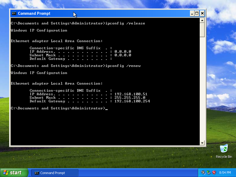
In Host, type the command ipconfig /release in order to release the old IP address. And type ipconfig /renew to get the IP address from Cisco Router

HostA-2013-09-21-20-54-38


Based on the output from RouterA, what are two possible reasons for the failure?

$
0
0

Refer to the exhibit.

322


Hosts in network 192.168.2.0 are unable to reach hosts in network 192.168.3.0.
Based on the output from RouterA, what are two possible reasons for the failure?(Choose two)

A. The cable that is connected to S0/0 on RouterA is faulty.
B. Interface S0/0 on RouterB is administratively down.
C. Interface S0/0 on RouterA is configured with an incorrect subnet mask.
D. The IP address that is configured on S0/0 of RouterB is not in the correct subnet.
E. Interface S0/0 on RouterA is not receiving a clock signal from the CSU/DSU.
F. The encapsulation that is configured on S0/0 of RouterB does not match the encapsulation that is configured on S0/0 of RouterA.

Answer : E, F

E: If no clock rate found on DCE end or no keepalive message received , then the Protocol Status changed to down.
F: Also if RouterA Serial0/0 and RouterB Serial S0/0 configured with two different protocols (Example: HDLC, PPP), then Protocol status will be changed to down.

Incorrect Choices

A, B: If cable is faulty or RouterB S0/0 is administratively down, then Status of RouterA S0/0 also in down.
C, D: If incorrect IP address and Subnet mask configured, the protocol status or physical status never on down state.

How to recover Cisco Router/Switch Password

$
0
0

The following is the tutorial about how recover a Cisco Passwords (Example: Console Password, Enable Password, Enable secret, VTY Password. But no need to removing case or CMOS Battery)


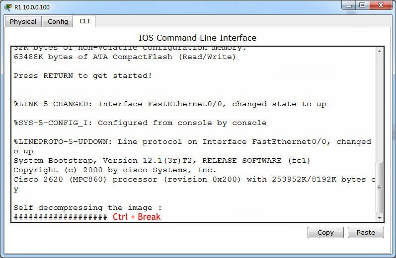
Step 1: Restart / Power On the Router “R1”

image

Step 2: Press Ctrl + Break, When the router is booting IOS. This key will interrupt the router boot process and prompt you ROM Monitor (ROMMON) Mode.

 password1


Step 3: Change the Configuration Register key to 0x2142 using confreg 0x2142 command. The key 0x2142 used to avoid coping configuration from NVRAM to RAM during next boot process.
Then restart the router using reset command

image


Step 4: After router restarted you will prompted for Initial Configuration. Type no to avoid Initial Configuration.

image 


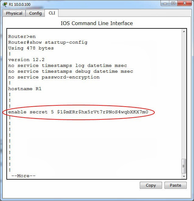
Step 5: Now the router with basic default configuration will be loaded. You can verify your passwords by show startup-config in Privilege EXEC mode.

password2 
password3


Step 6: Copy the Startup Configuration to RAM by using command copy start run.

image


Step 7: Now we can remove the password using Global Configuration commands. And the change the configuration register key to 0x2102 (default).

R1#configure terminal
R1(config)#no enable secret

R1(config)#line con 0
R1(config-line)#no password
R1(config-line)#no login
R1(config-line)#exit

R1(config)#line vty 0 4
R1(config-line)#no password
R1(config-line)#login
R1(config-line)#exit

R1(config)#config-register 0x2102
R1(config)#end

image


Step 8: Now save the current configuration to NVRAM by copy running-config startup-config command. And restart the router by reload command.
image

Finished. Now you can access your router with with no authentication.

Host A pings interface S0/0 on router 3. What is the TTL value for that ping?
$
0
0

Refer to the exhibit.

image

Host A pings interface S0/0 on router 3. What is the TTL value for that ping?

A. 252
B. 253
C. 254
D. 255


Answer : B


Explanation:

The TTL or Time-To-Live gives you an indication of the number of routers between the source and destination. The TTL is used to prevent an IP packet from looping inside an IP network and causing a network meltdown. The initial TTL packet value for an IP packet is 255 and then it is decremented by 1 each time it encounters a router. When this value reaches 0, the packet is discarded by a router. The TTL value is contained in each IP packet including ICMP packets. The TTL value given by the ping command is in fact the TTL value of an echo_response packet. By default, Windows will decrease the TTL by 128 and Ubuntu Linux by 192.

ping253topo

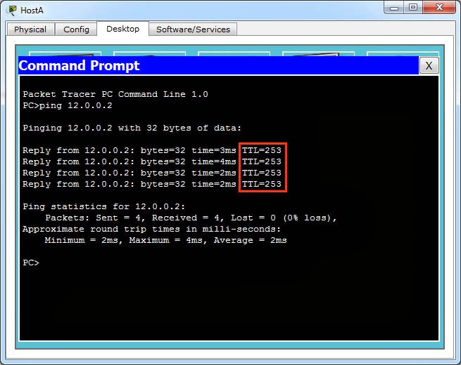
The above the exact topology of this questions. I used 10.0.0.1 for Host A’s IP address and 12.0.0.2 for R3 S0/0’s IP address. All router has been configured with EIGRP routing protocol. And following is the output of ping 12.0.0.2.

ping253

Now the TTL value is 253.

Difference Between SNMPv2 and SNMPv3

$
0
0

SNMPv2 vs SNMPv3

Internet Protocol (IP) networks use managing devices such as Simple Network Management Protocol (SNMP) to monitor network attached devices. In a computer network, a group of devices are attached, and they are managed and monitored by a manager. An agent, which is a software module in a managed device, reports information through the SNMP to the manager which has a Network Management System (NMS) that executes the applications that monitor and control managed devices.
There are seven SNMP protocol data units (PDU):

GetRequest– request to retrieve the value of a variable from the manager to the agent.
SetRequest – request to change the value of a variable from the manager to the agent.
GetNextRequest – request to find variables from the manager to the agent.
GetBulkRequest– enhanced version of GetNextRequest.
Response – reply from the agent to the manager through the return of variables.
Trap– simultaneous message from the agent to the manager.
InformRequest – simultaneous messages between managers.


snmp

There are three versions of SNMP:

1. SNMPv1, which is the network management protocol being used by the Internet.
2. SNMPv2, which is a revised version of the SNMPv1. It contains improvements in performance, confidentiality, security, and communications between managers. Its party-based security system is very complex, though, and has to be revised in order to be able to use it with the SNMPv1.
3. SNMPv3, which has added cryptographic security and new concepts, terminology, remote configuration enhancements, and textual conventions. Its new security features are:


It provides confidentiality through the encryption of packets to block intruders from the outside. It assures message integrity by protecting packets with a protection mechanism. It ensures that the message is from a reliable source.

The Request for Comments (RFC), a memorandum that describes methods, research, and changes that are applied to the Internet has given SNMPv3 full Internet standard and regards older versions as outmoded. SNMPv2 agents can be used as proxy agents for SNMPv1 managed devices. It has improved error handling and SET commands over that of SNMPv1. Its Inform features allows acknowledgement of the receipt of messages by the manager. SNMPv3, on the other hand, has a better security system. It ensures that the messages are read only by the designated recipient, and any messages that are intercepted by unauthorized users are garbled especially if they are forwarded through the Internet.


Summary:

1.Simple Network Management Protocol version 2 (SNMPv2) is a managing device used to monitor devices in a computer network while the Simple Network Management Protocol version 3 (SNMPv3) is the latest version of the SNMP.
2.SNMPv2 has a complex party-based security system while the SNMPv3 has a cryptographic security system.
3.SNMPv2 agents can be used as proxy agents for SNMPv1 managed devices.
4.SNMPv2 introduced the Inform features which allow acknowledgement of the receipt of messages by the manager while the SNMPv3 introduced an enhanced security system that authenticates messages and ensures their privacy especially if they are forwarded through the Internet.

Drag and Drop Questions

$
0
0

Question 1
Drag the security feature on the left to the specific security risks they help protect against on the right. (Not all options are used.)

image


Answer :

image


Question 2
Routing has been configured on the local router with these commands:

Local(config)#ip route 0.0.0.0 0.0.0.0 192.168.1.1
Local(config)#ip route 10.1.0.0 255.255.255.0 192.168.2.2
Local(config)#ip route 10.1.0.0 255.255.0.0 192.168.3.3

Drag each destination IP address on the left to its correct next hop address on the right


image

Answer:

image


Question 3
The left describes the types of cables, while the right describes the purposes of the cables.
Drag the items on the left to the proper locations. (Not all items can be used.)


image


Answer:

image


Question 4
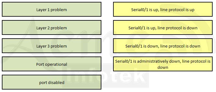
Drag each category on the left to its corresponding router output on the right. Each router output line is in the result of a show ip interface command. (Not all categories are used.)

image


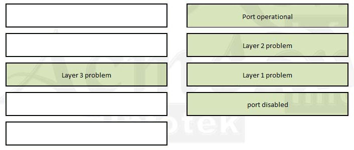
Answer:

image


Question 5
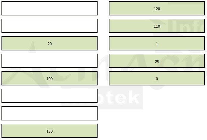
Drag the Cisco default administrative distance to the appropriate routing protocol or route (Not all options are used.)


image


Answer:

image
Viewing all 26 articles
Browse latest View live